This article taken from Gateway NMRA by John Carty
We have all seen this before. You visit a beautiful miniature layout overflowing with detailed scenery and eye-catching vignettes. The track work functions impeccably. Then comes the train around the bend: a perfectly detailed Mikado followed by a tank car full of gasoline, a boxcar loaded with nitroglycerin, and a gondola toting telephone poles in front of the caboose.
Due to some oversight, this pretty little local ends up on a siding smacking the hind end of the string of boxcars, which occupied said siding. What a mess.
In the real world this accident creates one impressive crater as the sudden deceleration launches the telephone poles through the back end of the boxcar ahead. The nitroglycerin then performs an impressive pyrotechnic display abetted by the gasoline. The resulting excitement leaves two questions: “Where is the train?” followed by “What siding?”
Although this kind of accident commonly occurred in the infancy of railroading, the railroads have adopted practices over the years to ensure the safety of equipment, cargo, personnel, and the public by minimizing the risk of such accidents occurring. Both the American Association of Railroads (AAR) and the United States Department of Transportation (DOT) each developed a set of standards to avoid such spectacular pyrotechnic displays. These standards balance safety in transit with costs and safety in switching and handling requirements.
The AAR classifies a “no-problem train” as one with less than 4,000 tons total train weight operating on less than 2% grades and 8 degree curves. In the modeling world we attain the first, but the second and third are usually compromised beyond any chance of recognition due to space constraints.
In this article, I will outline the considerations of forces, car types, motion, and loads, governing the prototype and then examine applications to the miniature version.
Forces
Each car and locomotive exerts two forces on the track. First, the vertical force (V) consisting primarily of the units weight presses down on the top of the rails. Second, the wheels exert a lateral force (L) outward from the center of the track via the flanges and tires of the wheels. (Fig. 1) As a side note, The cross-section of wheel for a railroad car or locomotive bears the shape of a cone. Each car or locomotive exerts both of these forces on the track and as a simplification, when the lateral force exceeds the vertical force the cars tend to leave the track. On the other hand, many forces act on each car and locomotive as it moves along the track. First the train and track resist motion in a manner related the property of inertia. This train resistance arises from several sources. First the grade allows gravity to pull the train downhill. This force could hold the train back or pull it forward depending on whether the grade in question slopes with or against the direction of travel. These forces take the form of slack action, which will be examined further below.
The curvature of the rails also adds to the resistance of the train. As the train travels along the curve, the wheels rub against the rails increasing the frictional force. Acceleration (or deceleration) creates drag when starting or going up hill and pushing when stopping or heading downhill. Additionally, the turning of the wheels in their journals creates another frictional force, which when combined with the rolling of the wheels on the track, creates rolling resistance. Tractive effort measures the force exerted on the coupler by the locomotive at the coupler to overcome train resistance.
To stop a train requires braking forces. Controlling downhill speed also requires braking. First dynamic braking occurs when the traction motors of the locomotive cease to turn the wheels, allowing the wheels instead to turn the motors transforming them into generators. This creates excess current, which the locomotive dissipates through resister grids, generating considerable heat. Since dynamic braking occurs at the front of the train, braking forces concentrate immediately behind the locomotive.
Booster engines positioned mid-train add additional concentrations at the back of each set of locomotives. A pusher on the other hand creates drag at the tail of the train. The automatic brakes control the brake shoes applied to the wheels of each car and locomotive in the train. Although this appears instantaneous on a short train, the air moves at merely the speed of sound, creating a delay from the source (locomotive) to the brakes on each car. This creates a cumulative application of braking forces instead of a steady application, as the front cars begin braking before each car following. The independent braking affects only the brakes on the locomotive. This affects the train in a similar manner to the dynamic brakes.
The above forces directly affect the slack in the train. Slack represents the range of travel of a coupler in the draft gear with relation to the car on which it is mounted. A standard coupler moves within a range of approximately six inches. Various appliances may extend or limit this range, however. The slack in the coupler allows the locomotive to start the train a single car at a time, thereby easing the tractive effort required to overcome the inertia and friction in the wheels of the standing cars, which exceeds that of cars in motion. In other words the locomotive literally starts the train moving one car at a time.
Effects of Excessive Train Forces
Forces exceeding the capacities of appliances create a variety of problems. Two types of excessive forces exist: steady state and transient. Steady-state forces apply to the train and track over a relatively long period of time. Pulling a train up a heavy grade presents one example. High steady-state forces result in four problems: train separation, string-lining, buckling, and jackknifing.
Train separation occurs when the draft forces exceed the physical strength of the materials comprising the draft gear, causing the train to split apart. Usually the knuckle breaks, resulting in the intended protection of the draft gear and end sills.
Draft forces below that necessary to produce train separation tend to stretch the train into a straight line. This applies considerable forces to the inside of a curve. Under normal circumstances the design of the track allows it to withstand such loads. Combinations of cars possessing a high center of gravity or carrying light loads may produce a lateral load exceeding the capacity of the track or car resulting in string-lining (Fig 2). This may cause the inside rail to lie over, or the entire track structure may be yanked from the ballast toward the center of the arc of the curve. Additionally, wheels on the high side of super-elevated track may lift and derail, or the cars simply tip over the lower rail. Another possibility provides for cars in the train to be lifted up and plopped on the inside of the curve, leaving little if any evidence on the rails at the point of derailment.
Buckling (Fig. 3) results from forces similar to string-lining but acting in the opposite direction. This causes the cars to skew off the rails. Cars under draft forces varying between loads and empties exacerbates both string-lining and buckling.
Like buckling, jackknifing (Fig. 4) results from forces within the train acting toward each other beyond the capacity of the vehicle and track. Under such conditions cars attempt to fold like a jackknife. Lateral forces produced by this condition act in a similar manner to those involved in string-lining, but in the opposite direction. A typical situation of jackknifing sees a wheel climbing over the rail or the rail itself turning over, eliminating the ability of the system to support the train. Combinations of long and short cars coupled together aggravate the situation.
In addition to steady-state forces, transient forces may also reach excessive levels. By definition transient forces apply for relatively short periods of time, due to changes in grade or acceleration. Three terrain features tend to generate transient forces: crests, sags, and undulating terrain. First, crests mark the change from uphill to downhill, transforming free play from slack-out to slack-in. When forces become excessive, cars may jackknife.
The opposite of crests, sags, adjust slack from running-in to running-out. An excess of such forces may break a coupler or derail a train by string-lining. Larger differences in gradient, higher train speeds, faster rate of braking at the crest, and the rear of the train containing most of the tonnage magnify the transient forces at both the crest and sag.
The last area, undulating terrain combines the worst of both worlds. In such an area crests and sags alternate. A long train may find parts of itself in both conditions at the same time.
Switch crews must assemble the train for this train with great care to achieve optimal make-up. Additionally, crews require great skill in acceleration and braking. Extremes of both pulling (draft) and pushing (buff) forces may occur when cars in the train are either all empty or all loaded. Unit trains, including coal, grain, and juice (Tropicana); provide ample examples of these phenomenon. Given that virtually no railroad operates on a tabletop, significant concentrations of force may occur anywhere in the train. Additionally, cushioning devices may magnify the above effects by virtue of increased travel in the draft gear.
Car Types
The basic 40-60 foot car on two trucks presents few additional problems beyond the obvious load or empty condition. Multiple platform cars, such as articulated well cars, require some consideration. The cars themselves represent an improvement in the geometry of railcars. Due to low tare weight, however, required special consideration when empty as the L/V ratio increases. Single axle cars also posses relatively low tare weights, requiring care to be taken to avoid placing ahead of heavy loads when making up the train. Combinations of long and short cars create a critical situation at crossovers when the track between the lead curves fall short of the length of the longest car. This situation deteriorates with sharper turnouts. Sharp curves also exhibit this dilemma. Cars protected with end of car cushioning may require limits in the size of blocks of such cars or be blocked behind loads with conventional couplers.
Harmonic Motion
Consideration of three kinds of harmonic motion influences the makeup of a train: truck hunting, pitch and bounce, and harmonic roll. Speed influences all three types of harmonic motion, while trailing tonnage and train length rarely do.
First, truck hunting describes an instability, which usually occurs in lightly loaded or empty cars traveling over forty-five miles per hour. Worn trucks may cause this motion to occur at speeds as low as thirty-five miles an hour. Truck hunting creates yawing and twisting about the center of the car. Ironically straight, welded rail often exacerbates this effect. Poor alignment and surface, however, increase the likelihood of a “hunting” car actually derailing.
Secondly, pitch and bounce refers to extreme vertical displacement of the ends of cars. Like truck hunting, pitch and bounce tends to occur at speeds over forty-five miles per hour. Adding to the fun, motion may occur in or out of phase. In other words adjacent ends may move in the same direction or in opposite directions. Cars containing loads lacking sufficient dampening exhibit this problem most often. Ore jennies and short tank cars, also known as “beer cans”, also suffer pitch and bounce more often.
Lastly, low speeds ranging from ten to twenty-five miles per hour may create harmonic roll, which also bears the name “rock and roll.” Unlike the other two forms of harmonic motion, heavily loaded cars with a high center of gravity suffer this effect more often. Additionally, less than prime track contributes to this ailment. Half-joint staggered rail causes this problem more often, preying on cars whose truck centers nearly match the length of each piece of rail. A fifty-foot highsided covered hopper containing grain or other dry-flowing material most typically falls victim.
Car Placement
All of the above forces contribute to derailments, something the railroads and ICC obviously seek to avoid. Bearing this in mind, how should cars be placed in the train?
First, heavier cars should travel near the front of the train. As a corollary, light and empty cars should populate the rear of the train. This places loads near the locomotive easing coupler strain and also prevents string-lining. It also prevents buckling and jackknifing during shoves, when the engine pushes light cars into loaded cars at the end. Also individual very light cars should not be located between heavily loaded cars to avoid lifting during moves. Additionally, mixing of light and loaded cars exacerbates problems created by terrain.
Secondly, railroads block cars according to destination. This saves switching along the route and at the destination. It also helps avoid hazardous combinations or potential contamination of valuable lading. For example one would not place a car loaded with vegetables in ventilator service adjacent to a car full of green (uncured) hides or a load of toluene beside a load of nitric acid.
Third, railroads block cars together of similar length. This helps to prevent problems at crossovers and “S” curves.
Hazardous Materials
The last area of consideration concerns loads of hazardous materials. The previous three considerations function in deference to the requirements of shipping hazardous materials. The Interstate Commerce Commission divides hazardous materials into four groups. The first group consists of class A explosives. Next, group two contains explosives from classes B and C, compressed gases other than poisonous gases, flammable liquids and solids, oxidizing agents, poisonous liquids, and corrosive materials.
Poisonous gases and liquids comprise group three. Finally, group four covers radioactive materials. A car carrying hazardous materials requires at least five cars between it and a locomotive or occupied caboose. If the length of the train does not permit such separation, cars carrying hazardous material must be located near the center of the train.
Additionally, explosives must always travel at the center of the train, as well as not adjacent to the flammable lading (placarded “INFLAMMABLE”).
A car conveying material from one group may not be located next to a car containing material from another group, thus requiring buffer cars. Open cars such as gondolas containing a load extending beyond the ends or that might protrude beyond the ends if shifted as well as loaded flat cars other than TOFC, auto carriers, and those equipped with tie down devices for vehicles may not be placed next to cars carrying explosives or tank cars carrying hazardous materials.
Additionally, cars containing hazardous materials may not be adjacent to cars utilizing mechanical temperature controls or operating an internal combustion engine. Placement of cars however should avoid extra switching. The table summarizes the restrictions, which apply to each type of material.
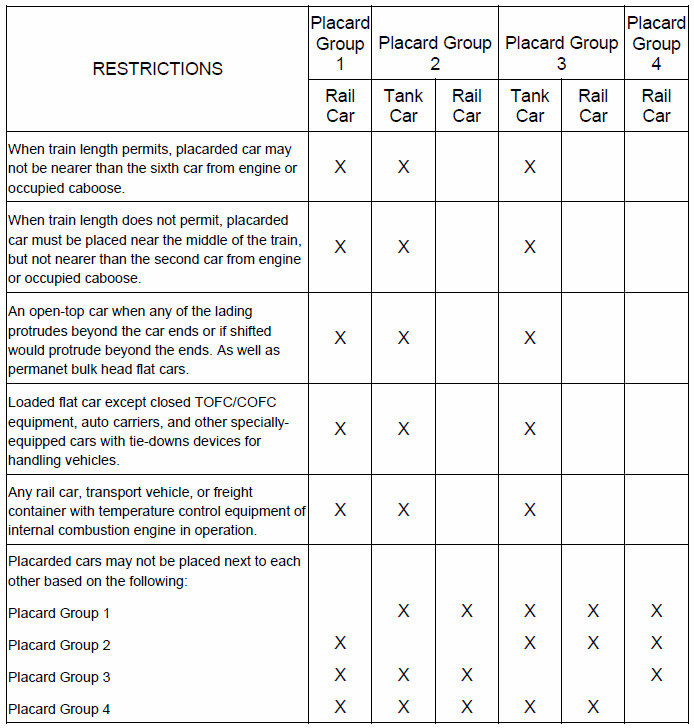
Derailment remains one of the greatest concerns for railroads. The derailment of a car carrying hazardous materials poses not only the problem of recovering the car and its lading, by also the threat to the public as well as railroad employees. To this end such cars should be placed in the part of the train with the least potential for derailment. Studies commissioned by both the AAR and ICC found the last quarter of the train to be safest followed by the first then third, with the second quarter of the train having the greatest potential for derailment. With this in mind, the last quarter presents the greatest danger in an accident involving another train overtaking and colliding with the rear of a train carrying hazardous materials. Additionally, placing cars loaded with hazardous materials after empty cars increases the potential for buckling and jackknifing. As a note, hazardous materials may only be carried by passenger trains in baggage cars with both placard and attendant.
Finally, although all of the above guidelines provide best-case solutions, switching should be minimized. Each switch movement represents an opportunity for mishap. Since safety is always a priority, the making up of a train represents a compromise between perfect placement and minimum handling. This compromise, however, must still protect the crew of the train in both the locomotives and caboose.